Welcome to ProDSP!
Thank you for paying a visit to our stand!
Below, you’ll find an introduction to our PCB rulers, their functioning and if applicable, the details required for mounting.
LOGIC variant
Board function:
Implements logic functions by using NAND gates. The two inputs (A and B) may be changed using push buttons, meaning the logic values of ‘0’ and ‘1’ when released or pressed, respectively. The values of the various logic functions are shown in the corresponding LEDs. The circuit is powered via a micro USB connector.
Implemented logic functions:
- A
- B
- NOT(A)
- NOT(B)
- A AND B
- NOT(A AND B)
- A OR B
- NOT(A OR B)
- A XOR B
Connection diagram:
![IN PCB RULER LOGIC V1p0 [No Variations] SCH 2023 03 13](/images/kellekek/Ruler/IN_PCB_RULER_LOGIC_V1p0_[No%20Variations]_SCH_2023-03-13.jpg)
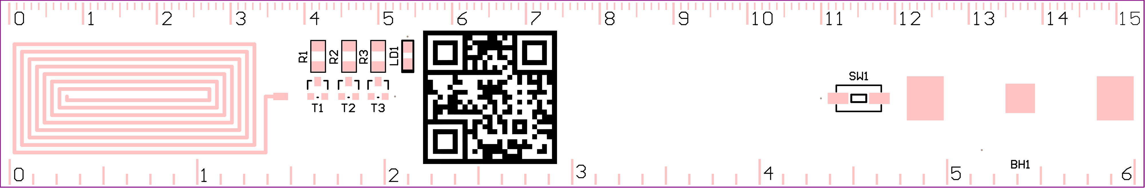
Mounting diagram:
![IN PCB RULER LOGIC V1p0 [No Variations] AsmDoc 2023 03 13](/images/kellekek/Ruler/IN_PCB_RULER_LOGIC_V1p0_[No%20Variations]_AsmDoc_2023-03-13.jpg)
BOM:
| Designator | Quantity | Part Number | Comment / Name | Package |
| C1, C2, C3 | 3 | CAP SMD 1206 CER Y5V 10uF 10V |
10uF | 1206_CAP |
| CON1 | 1 | CON_USB _MICRO_A B_629105150921 |
WUERTH_6291051 50921 |
USB_MICRO _AB_WUE RTH_629105150921 |
| IC1, IC2, IC3 | 3 | 74HC00D,653 | 74HC00D,653 | SO-14 |
| LD1, LD2, LD3, LD4, LD5, LD6, LD7, LD8, LD9 | 9 | LTST-C170KGKT | LTST-C170KGKT (GRE) | LED_SMD _0805_GRE |
| R1, R2, R3, R4, R5, R6, R7, R8, R9, R10, R11 | 11 | RES SMD 0805 1% 680R |
680R | 0805_RES |
| SW1, SW2 | 2 | SW_DTSM 32N | DTSM 32N | SW_DTSM-32N |
AC DET variant
Board function:
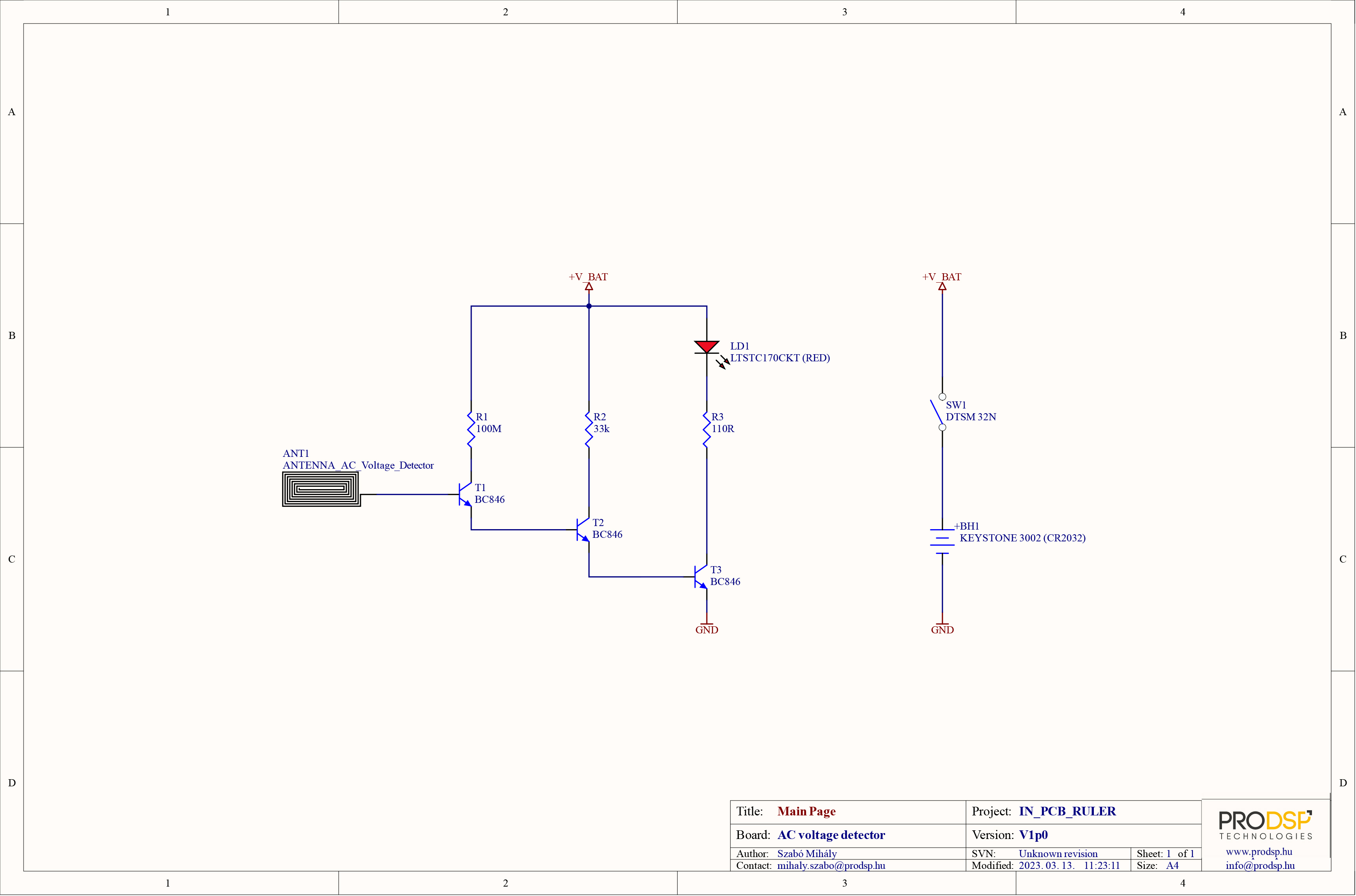
By keeping the push button pressed, a LED indicates the presence of AC voltage nearby. It is powered by a CR2032 battery.
Connection diagram:
Implemented logic functions:
BOM:
| Designator | Quantity | Part Number | Comment / Name | Package |
| BH1 | 1 | BATTERY_HOLDER _CR2032 | KEYSTONE 3002 (CR2032) | BATTERY_HOLDER _KEYSTONE_3002 |
| LD1 | 1 | 3SM3-SMD | LTSTC170CKT (RED) | LED_SMD_0805_RED |
| R1 | 1 | RES SMD 1206 5% 100M | 100M | 1206_RES |
| R2 | 1 | RES SMD 1206 1% 33k | 33k | 1206_RES |
| R3 | 1 | RES SMD 1206 1% 110R | 110R | 1206_RES |
| SW1 | 1 | SW_DTSM 32N | DTSM 32N | SW_DTSM-32N |
| T1, T2, T3 | 3 | BC846 | BC846 | SOT-23 |